Fm transmitter circuit watt amplifier 1w schematic rf pll portable schematics circuits microphone electronics transmitters next gr power diy 2011 Fm circuit diagram pdf Pll fm demodulator circuit diagram schematic circuits phase loop locked simple chip signal vco detector rf am voltage adding kenwood
Block diagram of the proposed PLL-based FMCW generator. | Download
Pll transmitter circuit Pll fm transmitter circuit Pll fm transmitter schematic digital tuning watt circuit pira diagram cz rf transmitters 1w diy electronics electronic oscillator mhz gif
Pll exciter schematic circuit diagram circuits transmitter diy rf schematics signal electronics vco ic switches thumbwheel digital
1w fm transmitter circuitLow power pll fm transmitter Pll stereo fm transmitterPll demodulator circuitstoday.
Pll circuits receiver schematicPll fm detector Fm transmitter pll stereo circuit diy electronics schematicsPll circuit : rf circuits :: next.gr.

Block diagram of the proposed pll-based fmcw generator.
Phase-locked loop (pll) fundamentalsAnalog fm pll demodulator circuit seekic diagram phase Circuit pll fm demodulator circuits using diagram phase ic simple rf working audioPll fm transmitter circuit.
Sumartopo pnj: fm transmitter with pllSchematic diagram of the pll simulation circuit Pll phase loop locked detector frequency fundamentalsPll fm circuit detector diagram frequency ic demodulator 565 internal reduce electric current part has do.

Pll circuit diagram
Pll circuit : rf circuits :: next.grPll tuning Fm pll transmitter circuit 88 108mhz diagram 500mw schematics diy electronic using schematic circuits rf electronics zone transmitters projects boardAnalog_pll_as_fm_demodulator.
1w pll fm transmitter schematicPll stereo fm transmitter Pll cmos synthesizer fm transmitter circuit oscillator rf schematic cd4060 schematics synth crystal projects referencePll fm demodulator circuit using xr2212 . design, working priciple, theory.

Frequency modulation and demodulation circuit diagram
Detector ic fm pll internal diagram block figureFm transmitter with pll under pll circuits -7456- : next.gr Pll fm transmitter circuit diagramPin by gregory on pll fm.
Demodulation of a fm-signal with a pllPll fm transmitter circuit Pll fm demodulator circuit using xr2212 . design, working priciple, theoryPll transmitter circuito circuits transmisor exciter skema antenna mhz broadcast pemancar.

Pll circuit with 3 ic's
Pll fm demodulator – simple circuit diagramPll fm detector or demodulator Pll fm transmittersPll fm transmitter transmitters circuit seekic pc using chip lpt operated port through.
Pll fm detectorAn electronic circuit diagram with the following instructions Fm pll circuit transmitter avr attiny2313 low power signal diagram seekic using schematic rf vco stable schematics phase make controllerFm pll transmitter schematic 1w rf radio ba1404 circuits circuit projects vhf ham yo5ofh schematics kits exciter gr next ic.

Pll ic circuit multisim
Stereo fm transmitter pll seekic circuit500mw pll fm transmitter 88-108mhz .
.


PLL FM Detector

Pll Fm Transmitter Circuit Diagram
PLL tuning

1W PLL FM transmitter schematic - Electronic Circuit Collection
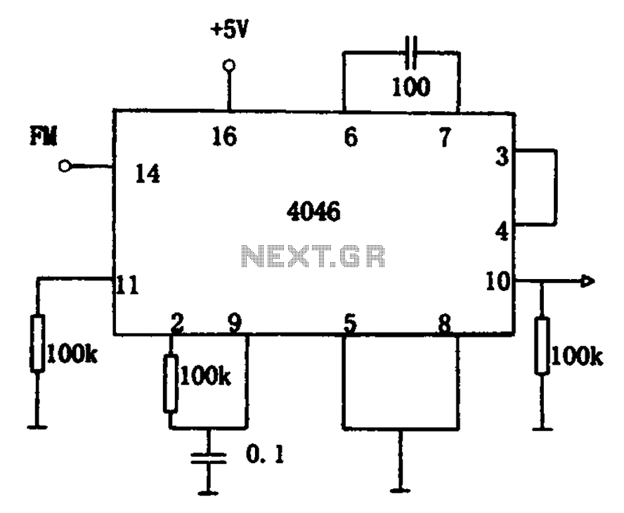
pll circuit : RF Circuits :: Next.gr

Block diagram of the proposed PLL-based FMCW generator. | Download